Wednesday 29 August 2012

All in one Prototyping PCB assembly

The assembly of the PCBs finally got started over the weekend and so far I'm pretty pleased with them, I've spotted a couple of minor issues so far but nothing that can't be fixed with a sharp knife some wire and a soldering iron.

Eagle files can be found here, they are version 2 with the power supply fixed and an added higher power 5V regulator.

So far I've only tried the ATMega 328p and it's peripherals, the ATtiny84 can wait until next weekend.


Firstly I added all the resistors, they need to be quite small resistor, physically that is, as I only used a 5mm lead pitch package.  I then added the voltage regulators so I could check that power appeared correctly at all the places it should do and at the right level.

This is where I spotted my first error, originally I'd planned to feed the 3.3V regulator from the output of the 5V regulator but then for some strange reason I changed it so both regulator inputs were tied together, unfortunately this meant that when the USB to serial (FTDI) was connected it wouldn't supply the 3.3V regulator and therefore the processor wouldn't be powered.

I cut the track from the supply to the input of the 3.3V regulator and wired it to the output of the 5V regulator. this meant that the FTDI 5V was fed into the 3.3V regulator and supplied the processor.


One of the first things I tried when I got the boards was to plug in the GLCD from Jeelabs as I use this quite a lot, luckily it fit perfectly and it even works.


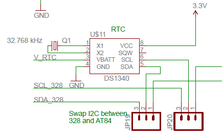
Today the RTC chip arrived with a clock crystal and was soldered in place, not as difficult as I thought it would be.
Added a CR2032, loaded the RTC sketch and used my RTC time setting app for the PC to set the time and it worked fine.

So far so good.....

Saturday 11 August 2012

328p / ATtiny84/85 Programming Adapter PCB

The Multi programming add-on PCB for my USBTiny programmer arrived today.

Just built one to test.

The ZIF socket came from HongKong via Ebay.

Just connect it to the ISP programming cable from the programmer, make sure the programmer can supply 5V and then you ca program your own boot loaders or sketches and use the Arduino IDE to program the ATtiny84s.

If you want the schematic or PCB files (Eagle CAD) let me know in the comments, also I have some surplus PCBs to requirements so if you want one then I may let some go a cost plus postage and packaging.

Link to the Eagle sch and brd files here.


Friday 3 August 2012

328 All in one Schematic

Here's the schematic for the PCB on the earlier post. PDF of schematic


The schematic is laid out in sections: -

Dual power supply
Various power supply options
RTC connected to 328p or ATtiny84
Two I2C ports from 328p (should work with I2C Jeeplugs)
Prototyping area


As usual feedback is welcomed.


Wednesday 1 August 2012

All in one Arduino Prototyping solution

I've been interested in the open HW/SW platform "Arduino" for some time now, it has re-ignited my interest in electronics, which hasn't been at the forefront of my hobbies for some time.
My main interest lay in the area of computers and software but with the discovery of the Arduino platform I was able to merge the two together.

I've bought a few pieces of hardware from various sources and  had a dabble at making my own hardware (mainly copied  based from what others have already done).

Anyway I decided I needed a project of my own to get my teeth into, I wanted to learn how to use the Eagle schematic capture and PCB layout software and after discovering Seeedstudio and their very keenly priced PCB manufacture, I decided to make a general purpose PCB that would allow me to tinker with both the ATMega 328 and the ATtiny84 processors along with various extras.

This board isn't aimed at a final solution but more an electronics breadboard much like the old Tandy electronics kits I used to play with many, many years ago.

Basic Features

  • Independent ATMega328p and ATtiny84 on the board
  • Each having its own RFM12B and ISP programming connector.
  • Twin power supplies, 5V and 3.3V with the option of using a CR2032.
  • A series resistor option for measuring supply current, jumpered out if not required.
  • A prototyping area.
  • A 4 port layout like the Jeenode (so I can plug in my GLCD).
  • A RTC (DS1307 3.3V)
  • Two I2C ports connected to the 328P with 5V and 3.3V (should work with Jeelabs plugs)
  • FTDI connector (328p)
I've not ordered the PCBs yet as I'm fine tuning the board still but should be doing it in the next week or so.

PCB
Comments welcome.

Three button WiFi Remote

Using the power control circuit from the Wirelesse door/Window sensor I have designed a simple 3 button WiFi remote with the intention of co...

Popular Posts