Showing posts with label Arduino. Show all posts

Tuesday, 21 October 2025

Testing LoRA transmitters and receivers

I've wanted to have a play with 868MHz LoRA transmitters for some time now but never got around to it until,  a while ago, I did an hardware design and PCB for someone wanting a prototype remote sensor as part of a security system to monitor inclination levels and transmit them over longer distances than WiFi can reasonably achieve.

I chose the Seedstudio Wio-E5 for the prototype connected to an ESP32 S3 and it was succesful as a testbed for further development. 

I know some of you reading this will be saying that you can just buy the HELTEC modules and similar modules but, as usual, I want to learn myself and also use up some of the modules I've bought in the past and never got around to using.

For my own design I wanted a simpler solution that I could use for outbuildings (shed) to monitor the status of the door and also the ambient temperature, the requirements were: -
  • Cheap to build
  • Last a very long time on a battery
  • Have a good range, relative to WiFi
  • Not using Meshtastic just sending a datapacket when triggered
  • Use a DS18B20 Temp sensor
  • Have an I2C connection for other sensors or a screen
For the power control I used the same trigger logic  circuitry I used on my WiFi window/Door sensor  which means that the LDO is enabled when the reed switch opens or closes and when the code is finished sending the datapacket it shuts off the power to itself using a GPIO.

I have made three different variants of the PCB to use different processors: -
  • An adapter PCB to connect an Xiao ESP32-C3 or S3 (or other Xiao module?)


  • A transmitter using an ATMEGA328p

  • An adapter to connect the Wio-E5 to a Waveshare 1.47" Display module based on an ESP32-C6


The other thing I'm testing out for these projects is AI, I've tried ChatGPT for writing Arduino code for ESP32s etc. without much success but I thought I'd try out the new Google Gemini Canvas AI and I was blown away with the code it generated, it's not 100% perfect but unlike ChatGPT it remembers it's mistakes and doesn't make them twice.  It's not a cheap option at £18.99 ($25) per month but you also get 2TB of storage.

Within a couple of hours (total prompt writing time)  I had working code for all three options, the AI sometimes needed help with the different pins used on the different ESPs for serial connections and there were a couple of inconsistencies between the transimitter and receiver code when I switched on encryption of the data packets but by pasting the debug serial code from the PC into the prompt window the AI was able to track down it's mistake and fix it.

One of the biggest time saving things about using the AI to generate the code is that once the screen setup is complete it lays out all the text for you, no more counting pixels to determine where everything goes and when the screen refreshes it creates the code to draw a rectangle over the existing code to clear out any left over bits of text if the newer text is shorter in length.

I also added a web page option to the receiver by just asking the AI to include a web page with the same information that's displayed on the screen.

I will post the code and the PCB details on my GitHub page in the next few days, I'm making some corrections to the ATMEGA 328p version before I publish it to GitHub.


Sunday, 15 May 2016

Chronograph - Another option

Latest project update for 2026 here


After printing the last model I ran out of the white filament and decided to give the black filament a try and was surprised to get a print that looks and feels a better print, I think it's an optical illusion though, black just seems to look better.

Anyway I decided to do another design of the enclosure one without the battery for those that just want to connect to their laptop via the USB cable and us the PC software from elsewhere in my blog.

This design is a bit smaller that the first as there is no battery, switch or charging cable, I did leave in the holder for the Bluetooth module so it can be used with the smartphone app but you will need to power it from one of those portable emergency batteries via a USB cable.

You can get the STL files from Thingiverse


I've also been making some changes to the Arduino sketch to improve the functionality, I've implemented the use of interrupts to trigger the measurements so that some other things can be done via the main loop like checking if the trigger beams are blocked.

Some other options may be possible like adding and SD card to store shot data internally and use you PC later to recover the shot data for analysis, If you use a long enough piece of aluminium you could add a thread to the end to fit you silencer to and just use you gun for the day and download the shot data later.

Monday, 9 May 2016

Chronograph completed - Finally

Latest project update for 2026 here


As anyone who's read this blog before will know, there's a common theme throughout, the DIY Chronograph I made for measuring the speed of an airgun pellet.

Well since getting a 3D printer I've finally managed to finish off the project and put it in a case, it's not often I actually put things in a nice case.

The first case with the Nokia display, it was a bit clunky and easy to break, when I dropped it that is!

Second attempt, this is the one I've been using.  This one uses the Bluetooth module to talk to an app on the phone here
Collection of bits held together with heatshrink
The final one, this one contains all the gubbins from the shot above inside the cover.
The end that screws on with the USB connector below and the front
view with the on/off switch and battery charge connector
Side View

This one uses the Bluetooth adapter and connects to an app on the phone and has an internal lithium Ion battery than can be recharged using an external supply and charging module, you can leave out the battery and use the USB connector of the Nano to power the chronograph from your laptop or a battery pack with a USB power output. (if you do this then the switch doesn't do anything)

The enclosure is essentially two parts, a carrier, that holds all the electronics and a slide on cover.
Both parts are a push fit onto the aluminium tube (16mm Dia. x approx 100m long)

Parts list: -

Item

Source

Approx. cost

3D printed enclosure - Thingiverse www.3dhubs.com
www.shapeways.com
£10 - £20
Arduino Nano (could be mini pro etc.) Ebay £2
Slide switch Ebay£2
Battery (Turnigy Nano-Tech 600mah 1S 3.7v 35-70C Lipo E-Flite) Ebay £5
Aluminium Tube - 16mm OD Ebay £5
Bluetooth Module Ebay £4
3V to 5V converter (NCP1402-3.3V STEP-UP BREAKOUT) Proto Pic £4
JST wired plug connector Ebay £3 for 10 off
IR Emitter x 2


Ebay
Farnell
RS Components


RS= £2.25, 5 off
IR Detector x 2 Ebay
Farnell
RS components
RS=£5, 5 off
Arduino SketchHere Free
Android App apk file (from Aptoide store) Here Free

So around £44 to put together, £24 'ish if you can 3D print your own enclosure.
You could also do away with the battery and 3 to 5V converter if you powered it from you laptop USB or battery with a USB socket on it.

More images

Battery and PCB modules in place with the tube

Barrel end showing the USB connector

Front end showing on/off switch fitted
Inside the cover

The Bluetooth module wired to the Nano

Nano and BT module in the carrier

Everything wired up... nearly. 3 to 5V converter top left under the battery
Tried and tested and working OK, the app works fine and I'm looking to add a graphing function so you can see the performance over a string of shots.

Fritzing schematic

As usual feel free to ask questions and comment below.

Thursday, 28 January 2016

3D printed bezel for the Nextion LCD display

Prompted by a post on another blog I read I dug out the 2.4" Nextion LCD display and thought I'd give it another go and whilst looking around the Nextion website I found that they'd designed some 3D bezels for the different size displays they do.
Well, as I got a 3D printer at Christmas I thought I would print one out for my display.


The result wasn't too bad. I think the bezel had been designed with some fancy curves on the front edges and because I printed it face down they had quite pronounced bits of filament that had to be removed, I think I will modify the bezel in Tinkercad to make the face flat.
I tried to sand the face a little smoother but the PLA became slightly discoloured from the glasspaper I used.

The rear was quite good with some strengthening ribs included and I found some small screws that made a tight fit and held in the display.

Next step is to make a backing box for the bezel to fit into but I'm waiting until I finalise the design of the project so I know what depth I need in the case.
I got a quote from Shapeways 3D printing service to print this design and it was £7.65 plus postage, although the quality would be better than from my printer I'm quite happy with the quality and I suppose I could also paint it to get a better finish, I'd better google "painting PLA".

Sunday, 24 May 2015

Shortcut Keyboard - Extended

Just a quick update to my shortcut keyboard.
I really started to use this while at work and found it really useful but there weren't enough buttons so I had an idea to double the size by getting some new acrylic fronts and backs made that were double the width and held two PCBs next to each other.

There are enough inputs left on the Arduino to connect the second set of buttons so no need for another Arduino.

I use Sketchup a lot and now I can attach several commands to the second set of buttons.

Tuesday, 12 May 2015

Discovering Node-red Part 1

Trawling around the various Arduino interest sites and blogs I quite often discover some new and very interesting information on some new topics and some not so new but un-known to me.

Sometime ago I'd read about a visual interface called Node-Red for designing IoT information flows and I was interested but didn't have the time to investigate so it was put on the back burner.

I then found out about the very versatile ESP-8266 that is a very inexpensive WiFi adapter for Arduino that comes in several flavours and can host a web page.

Anyway whilst I was searching around for info on the ESP8266 I found an excellent blog by Peter Scargill (here) and on his blog he'd written some posts about a couple of very interesting topics, node-red and Grovestreams.  In this post I'll try to give you a helping hand by describing my efforts to get it all up and running.

Objective
My goal was to have the RPi receiving temperature data from an external Jeenode via 868MHz (EU) using a Jeelink plugged into the RPi USB port, this would then be sent to Grovestreams to graph and also have twitter and/or email alerts setup dependent on temp. values.  Please remember though that I'm a beginner at this not an expert so there might be better ways to achieve this....

First - node-red
This software appears to be a visual interface that utilises Node.js which is a platform built on Chrome's JavaScript runtime.  There is an explanation on the node-red web page on installing both node.js and node-red for PCs and the Raspberry Pi.

Step one - installation
I decided to install node-red on My Windows7 PC first and if I could get it working I would brush the dust of my RPi and fire it up, I installed Node.js following the instructions here and then installed node-red, I think the installation is a little tricky unless you're confident using the command window in Windows but follow the instructions and you should be OK.

Step two - Run node-red
Node-red is run from a cmd window, I ran it using "run as administrator" from the right click context menu, when you run it it starts a server on your PC at http://localhost:1880 and this brings up the visual editor for creating your flows.
This is what my flow eventually looked like, I have added some descriptive text after the screen-grab was taken.

The layout shows all the different nodes down the left hand side, the editing window (where the nodes are dragged to) in the middle, the node information and debug output are on the right hand side (not shown).

Each node has a set of properties relevant to its purpose, i.e. if you double click the serial port node you will be able to configure the port details.

These grabs are from the RPi installation, the serial port names on PC install will look slightly different.
First dialog after double clicking
Click the pencil icon to get the config dialog.

Full serial port config dialog
The next node is called a switch node which can direct data to different outputs based on the incoming data, I realised later that I didn't need two nodes as one node can be given two outputs by adding a second rule.
The message from the transmitter contains labels for the temp. values, Greenhouse and Outside, this switch node uses these labels to direct the temp. values towards the matching Grovestream node.
Double clicking on the switch node opens the config dialog and each time you click on the +rule button, bottom left, you will add another decision and output branch.
The message payload is directed to the relevant output but it still contains the label and I want to remove the label so the next "function" node removes the label leaving just the temp. value.
I must admit that this function node took me a while to configure correctly, I can handle a few different programming languages but Javascript is not my favourite, the function basically splits the payload into parts around the ':' these 2 parts are referenced as 0 and 1 in an array and the second part [1] is passed on from the function thus removing the text label.

The input is Greenhouse Temp:20.1 and the output is 20.1

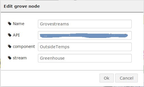
Once the value has been cleaned up it's ready to send off to my Grovesteams account, the Grove node has been written by Peter Scargill and the instructions to install it on Linux/RPi can be found here, for windows I downloaded the source files and placed them in a folder called "grove" in the following location: 


If installed correctly the purple node will appear in the list of nodes on the left hand side and is configured by double clicking.  Peter has a good "how to" guide on his blog here.


End of part one.


Thursday, 9 April 2015

Finished Shortcut Keyboard

The Acrylic tops and bottoms arrived yesterday for the keyboard so I thought I'd update the blog with a picture of the finished item side by side with the concept design,
I must say I'm quite pleased with it, the holes actually line up with the buttons :-).

Finished article
3D concept design


Saturday, 14 March 2015

Time saving Keyboard shortcuts for the PC

It's been quite a while since my last post but sometimes life throws you a curved ball and changes your focus for a time.  Anyway this little project came about due to a friend at work having to replace his PC keyboard but not being able to find one with single pre-programmed buttons for copy and paste, as did his current one, and I said " I can do that with an Arduino".

So the idea was to use an Arduino Leonardo clone that can emulate a mouse or keyboard and then program the keyboard sequences to be triggered from the press of a button.  Initially I was going to do just the copy, cut and paste but as I was going to use the standard 5cm x 5cm Seeedstudio PCB service I thought I could add some more buttons.

I decided to do a PCB with six momentary push buttons, mainly because they were what I had in my box of components.

The botom row, blue, black and white buttons are copy, cut and paste respectively and I assigned the red, amber and green buttons to change the background colour of Excel cells to match the button colour (this was a request from another friend at work who uses Excel a lot)

The buttons could have any combination of key-presses assigned to them I suppose, 'Ctrl+Z' for undo etc.

Circuit Diagram

The connections are a bit out of order due to pinswaps on the PCB!

I used the "Sick of Beige" 50mm x 50mm PCB template from Seeedstudio as I intend to use their Acrylic laser cutting service to create a top and bottom box to house the keyboard.
Keypad Concept

Due to space availability I placed the Leonardo PCB on the underside of the PCB, this did mean that it was a bit fiddly soldering the pins for the Leonardo as I didn't want any pins sticking through the PCB into the body of the switch so solder the pins first and make sure they are flush with the button side surface, NOT protruding.
Make sure the pins don't go too far through.
The pins can be trimmed

Everything is powered by the USB lead plugged into the PC and there is an optional SMD or 3mm TPH LED on the button side that connects to a PWM capable IO pin, I set this to indicate power at 7% duty cycle and then pulse to 78% duty cycle for 50mS whenever a key is pressed.

I've ordered the acrylic tops and bottoms from Seeedstudio but they've yet to arrive.

All the files, including the Eagle schematic, PCB, gerber files and the sketch are here.

Monday, 27 January 2014

Monitoring Data with the Arduino and ThingSpeak

In conjunction with my last post I thought I would monitor my hot water tank to track the temperature variations throughout the day, mainly to use the temp change to identify when someone has taken a shower and judge the need to heat the water up so there is some left for bed time (this will be done automatically by the Arduino code).

First I searched around for a free cloud data storage solution, I'd used Pachube/COSM previously but COSM had changed hands again and I found it was always a bit unreliable for me anyway.

I tried Nimbits.com first of all but found it quite difficult to get the UNO working with the code on offer and the help information was a bit of a mismatch with sample code not being up-to date with the latest API, having said that the forum was well supported and I got quick answers to my questions.  The main problem is that when I got it working my data on the graph contained random values which made the chart useless, I thoroughly checked the values that I was posting and the spurious data was not coming from me.  One plus was that they had an Android app on the Appstore so viewing the data was easy.

I then tried ThingSpeak, getting the UNO/Ethernet shield up and running was a lot quicker and I was posting temperature values within minutes.  Another nice feature was the ability to clear the current data from the channel, ideal when logging data during development that's not relevant to you actual job.

The chart looks nice, updates continuously and if you hover over the points a nice panel pops up with the data point details.

I've only just scratched the surface of ThingSpeak so there's still loads of stuff I just don't know about but it definitely enabled me to get up and running very quickly.  One thing missing from ThingSpeak was a dedicated Android App but after a couple of hours with App inventor I was able to put together a usable App that lets me view the data whilst out and about (sad I know).
It is also possible to embed the charts into other web pages using an Iframe.
There are plugins that can be created, there is a sample of a Google gauge but I still can't get it to work.  The forum doesn't seem to be as well supported as the one on nimbits, maybe there are less users.

The App inventor source can be found here. (updated to appinventor 2, import the aia file to app inventor 2)
The APK file can be downloaded here.
After running just type in your channel number and read key and click "set" and then "update"

Tuesday, 21 January 2014

Central heating control using SMS and the Arduino

One of the things I set out to do after discovering the world of Arduino was to make myself a clever controller for my central heating but, not unusually for me, my focus wandered here and there finding new and probably easier things do do with all these little gadjets.

I got back into air rifles which meant most of the blog, over the last few months, has been full of my various versions of a chronograph! I've tried loads of different displays and even Bluetooth to get the speed of the pellet to my phone.

Anyway, the weather turned cold again and thoughts drifted toward the central heating again but this time something a bit simpler, something to switch the heating or water on for a period of time without leaving the comfort of my arm chair.... yes I'm that lazy.

I'd dabbled with the 868MHz RF links, Bluetooth links but after coming across a post on nathan.chantrell.net I found a source for a cheap GSM modem.

My original thoughts were to bow to the latest fashion of "IoT" but my dealings so far with the Arduino and Ethernet interfaces had been less than perfect, quite randomly the data flow would just stop and I never got to the bottom of it.  The SMS solution appealed because I don't need a data connection or even a smartphone and can switch the heating on before I get home even if the raspberry pi and the arduino etc. are switched off when I'm on holiday.  The SMS route seemed like a good solid proven technology.

The Modem was an ex-equipment modem from some old BT security line monitoring equipment (search "redcare GSM" on Ebay) and I picked up mine for £4 including delivery, not too expensive, the SIM card was an old Giffgaff card from a previous phone which still had few quid in credit and my contract phone had unlimited texts ... so I thought I would give it a go.

The overall system laid out on the desk
The modem came with an external antenna and the 2x50 header still attached to the PCB which was quite lucky because the connector is a 1.27mm pitch IDC on a ribbon cable, to get connections to the modem I used a hot air gun to sweat off the SMD connector from the PCB.

I made the connections to a standard pitch connector so I could interface to the rest of the system, the pins are very small and it wasn't easy.

The idea was to connect the the relays in parallel to the existing relays in the controller so that the current timer based operations would continue but I could switch on the heating or water remotely.  The relays would be switched by the Arduino Mini Pro via a soft serial connection from the modem, there was also an I2C OLED status display and a remote temperature sensor for the hot water tank.  Initially the temp sensor would just monitor the water temp and be sent to the phone on request but I intend to use it later to give a finer control to the water temp (I might log temp to and SD card for a while to get an idea of usage).

The SMS control takes the form of a simple short message coded for heat or water and a duration, heat on for an hour would be H60 whereas heat for 2 hours would be H120 ... I said it was simple. Hot water just uses a "W" instead of a "H".  There is also the function to request the temperature of the water, this causes the Arduino to send an SMS containing the temperature of the water.


The control is done by an App on my Android phone but could be done just as easily by sending a text normally or there are some automation apps that would allow a pre-defined text message to be sent from an icon on your home screen.  Actually I suppose you could control your central heating system from within an app such as Tasker, Tasker would allow you to setup timed text messages to carry out the operation, this would only make sense if you get free text messages though.

The Arduino code checks the incoming phone number to make sure it matches the one(s) you allow to control the heating and the response to the hot water temp request is sent back to the requestor's phone.

I'm also thinking of connecting in to my alarm system to send out an SMS when it gets triggered.
That's all for now, I'll post a link to the Arduino code and the Android app in the next post.

There's plenty of technical information on the modem and links to a SMS messaging library on nathan's blog post here.

Please feel free to ask any questions or make suggestions in the comments below.

Wednesday, 6 November 2013

Another update to the OLED 1602 Library

I've made a change to the 1602 OLED library and also added a new function.

I've modified the sendString() function to now include the cursor position data and added a new function called sendFloat(), this allows you to send float data values, such as temperature, to the LCD ant it gets converted to a string before being sent to the display.

The sendFloat function takes the following parameters: float value, minimum length inc. decimal point, number of positions after the decimal point, the start column position, the start row position.

I've updated the library in my GitHub repository here

Please note that older sketches using the sendString() function will not work with the new library and will need to be altered.

/*
Demo sketch to display Strings and float values on the OLED
1602 display  from Wide.HK. This uses a Lbrary that I've
put together containing some basic functions.
 The I2C Address is set to 0x3C in OLedI2C.cpp
 Phil Grant 2013 www.gadjet.co.uk
 */

#include "Wire.h"
#include "OLedI2C.h"
OLedI2C LCD;
float digit;

void setup()
{
  Wire.begin();
  LCD.init();
  digit = 21.6;//This would normally be the float value returned from a temp sensor or other sensor
}
void loop()
{
  LCD.sendString("Temp",0,0);// now includes the cursor position data (col, row)
  LCD.sendFloat(digit,5,2,7,0);//Send the string to the display
  while(1);
}

Saturday, 26 October 2013

Updated wide.HK OLED 1602 Library

Thanks to Nathan from http://nathan.chantrell.net/ there is now a scrolling function in the Library.

This allows you to specify some text, the line to display it on and the speed to scroll it at.

Sample code by Nathan (modified by me to remove the scrollString function as it's now in the library).

/*
Scrolling demo on the OLED 1602 display from Wide.HK.
Uses Library by Phil Grant http://www.gadjet.co.uk
Scrolling by Nathan Chantrell http://nathan.chantrell.net
*/

#include  "Wire.h"
#include  "OLedI2C.h" // http://www.gadjetsblog.blogspot.co.uk/2013/09/oled-1602-display-and-library-for.html

OLedI2C LCD;

void setup() {
Wire.begin();
LCD.init();
LCD.clearLcd();
}

void loop() {
scrollString("Slowly scrolling text on line one...",0,200);
scrollString("and faster on line two...",1,100);
}


Download here: Updated OLED 1602 Library

Now on GitHub

Tuesday, 1 October 2013

PCBs for mounting the Chronograph sensors

Latest project update for 2026 here


I've not really done much on the Chronograph for a while but I thought I'd have a go at the latest PCBs I'd ordered.
When I mounted the LEDs originally I used some Veroboard.


This solution was quite fiddly so I laid out a PCB that would allow me to use SMD resistors for the IR LEDs and detectors and not require the wire links that I needed for the Veroboard.

I was also using some Bluetooth modules for connecting to my android smart phone, these were difficult to solder to as they are designed as surface mount modules.  It was cheaper to buy the modules without the mounting PCB so I created a 50x50mm (Seeedstudio standard) PCB with the two LED/detector mounting boards and the Bluetooth carrier board.


With the LED board I was able to create some long solder pad contacts to solder the legs to rather than using through hole technology which would've caused the legs to short out on the tube.  I did the same thing for the connecting pads.

The mounting PCB for the Bluetooth was just a carrier board with an LED to indicate the connection status, this could be left off if not required.

Unfortunately I ordered the incorrect Bluetooth module, I made the carrier PCB for the HC-06 module but ordered an HC-05 by mistake, the HC-05 can be operated in both master and slave mode but requires a button input to set it into AT command mode whereas the HC-06 is in AT command mode until paired, therefore it's easy to configure the baud rate, pass code and name using a terminal programme on the PC.

The HC-05 also uses a different output to indicate it's connection status, hence the additional wire on the PCB, this isn't required with an HC-06.

For those using Jeenodes I laid out the connector so that it would plug on the end of a Jeenode FTDI connector and work as a serial link, not tried it yet though.......

The EAGLE PCB design files can be downloaded here, feel free to use/modify etc.
Link to the Bluetooth module on Ebay here.


Sunday, 29 September 2013

OLED 1602 Display and library for the SSD1311

Following on from the last post, the OLED 2 line 16 character display arrived from Hong Kong.


The display uses I2C to connect to the host and will work at 3.3 or 5V so is ideal to use with an Arduino board.

The supplier WIDE.HK supplies some sample code to get it running in the form of a QR code on the packaging that links to the the code and a couple of PDF datasheets.

The code uses a long winded method to initialise and write to the display, but it gets it working.

I have been thinking it was about time I learned how to create a library and this gave me the reason to give it a go, as well as not being able to find a library for this device anywhere on the web.

The very basic Library can be downloaded here, please remember this is my first attempt at creating a library, it works but I imagine it needs more functions adding before it becomes very useful.

Library updated 7/11/13 see here.

Here is the demo code I wrote using the library: -
/*
Demo sketch to display text on the OLED 1602 display
from Wide.HK. This uses a Lbrary that I've put together
containing some basic functions.
The I2C Address is set to 0x3C in OLedI2C.cpp
Phil Grant 2013 www.gadjet.co.uk

Sketch updated to work with new library 7/11/13
*/
#include  "Wire.h"    
#include  "OLedI2C.h"  
OLedI2C LCD;
void setup()
{
  Wire.begin();
  LCD.init();  
}
void loop()
{
  //Set cursor position to col and row, top row is 0, first col is 0
  // no longer required LCD.cursPos(4,0); //(col,row)
  LCD.sendString("Gadjet's", 4, 0);    //("String", col, row)
  // no longer required LCD.cursPos(6,1); //Set cursor position to col and row 
  LCD.sendString("BLOG", 6, 1);   //("String", col, row)
  while(1);
}

As usual, feedback welcomed, use the comments if you found this library useful ...... or not.


Monday, 23 September 2013

Microduino OLED Display

Having read about the Microduino on Kickstarter I thought it looked familiar and tracked down where I'd seen it before, on a website http://hobbycomponents.com/index.php/dvbd/microduino.html unfortunately there seems to be a bit of a dispute between Hobbycomponents and the Microduino people so they aren't selling them any more.

They are offering you the chance to win one though because they've got loads of stock left.

Anyway I was lucky enough to get one of the OLED LCD displays before they stopped selling them, that's the reason for the post in the first place.

The display http://hobbycomponents.com/index.php/dvbd/microduino/microduino-oled-display.html looked like a good display for a reasonable price and I liked the promise of really good contrast and low power consumption when compared to other non OLED illuminated displays.


The display uses I2C to communicate with the Arduino so not many pins required to drive it and I really like the fact that it has some good solid mounting holes on it, so many displays out there seem to forget this requirement.

The first thing I needed was a library to get it up and working and  tried a couple before I found one that worked, the library covers a vast number of LCD controllers and allows the use of loads of different fonts.

The library can be found here https://code.google.com/p/u8glib/

The library does use a chunk of available flash memory but there's still some left over for your code but you might struggle if it's a huge application, I believe there are other libraries out there and they may use less resources.

Using the examples available and after adding the library you'll need to un-comment the line for this display relevant to your display, I used this one: -

U8GLIB_SSD1306_128X64 u8g(U8G_I2C_OPT_NONE); // HW SPI Com: CS = 10, A0 = 9 (Hardware Pins are  SCK = 13 and MOSI = 11)

A modified version of the hello world example with a simulation of what the Chronograph display would look like can be downloaded here.

I really like the look of these OLED displays and I've found another one on ebay I like
It's an OLED version of the classic 1602 LCD, now I'm just waiting for the postman to get here from China!

Thursday, 22 August 2013

MegunoLink serial monitoring software Part 1- Graphing Temperature data

Some time ago I received a newsletter with some information on a piece of software called "MegunoLink" this software is basically a Swiss army knife for dealing with serial Comm's from the outside world.

I've been using it for a couple of weeks now and it's capabilities are wide ranging so I'm going to break up the review into bite-size chunks.

There is a 7 day fully functional version of the software you can download to see if it meets your requirements.

The software is modular and has a separate screen for each of its features, here's a few: -
 - Manage the serial ports, you can have multiple ports setup.
 - Monitor the raw data received by the comm port.
 - Create buttons etc. to trigger the sending of data out of the port.
 - Create a Google map of the location received over the serial port.

The most useful features for me were the ability draw plots based on X,Y data or time based data, using the PC clock for the X coordinate.

The premise of the software is that the source data includes the structuring information as well as the actual data.

The example I'll use is my application for monitoring two temperatures and a battery level from a remote transmitter via a receiver connected to the PCs USB port.

Although the website gives plenty of examples they didn't quite match up to my requirements so there was a bit of trial and error until I got it working, I also sent a couple of questions to the support which were promptly answered.

The task was to plot two temperatures over time and also the remote battery level.

Both of these required a timeplot setting up, first the Arduino code: -

 //Send data to megunolink graphing software on the PC
  Serial.print("{TIMEPLOT:"); *This tells Megunolink that the following data is for the timeplot graph
  Serial.print("Temperatures"); *This is the name of the channel, this will appear on the selection dropdown at the top of the graph
  Serial.print("|data|"); *This tells the timeplot that the data is a single datapoint
  Serial.print("Inside Temp"); *This is the name given to the series line on the graph
  Serial.print("|T|"); *This tells the software to add a timestamp to the datapoint, from the PC time.
  Serial.print(inTempC,1); *This is the actual data to plot on the graph, to one decimal place.
  Serial.print("}"); *This is to close the data packet.

The actual message sent over the serial port looks like this

{TIMEPLOT:Temperatures|data|Inside Temp|T|inTempC,1}

I also create a similar message for the second temperature

  Serial.print("{TIMEPLOT:");
  Serial.print("Temperatures");
  Serial.print("|data|");
  Serial.print("Outside Temp");
  Serial.print("|T|");
  Serial.print(outTempC,1);
  Serial.print("}");

This sends the outside temp. to the Timeplot using the same channel name but a new series name, this way both series will appear on the same graph when you select Temperatures from the dropdown box in the Timeplot window.
Below you can see an image of the graph, which was exported from MegunoLink.


You can also open multiple windows that appear on separate tabs, which you can name, so you can have one Timeplot tab for temperatures and another one for battery level, this helps because changing the channel selection from the dropdown box from Temperatures to Battery level has some confusing results, the trace drawn so far for the previously selected channel stays on the chart but no longer plots any points and the newly selected channel starts to draw it's data points.
Along the top of the chart there are a row of option buttons to edit the properties of the chart and any series lines, just make sure you've selected the series before editing it.
left to right - select the serial port, select the channel, edit chart, view summary of data, display/hide legend, run chart like chart recorder, edit series properties, remove single series, remove all series, zoom, pan, zoom all and zoom last

I'll list some more features in the next post, there are quite a few left yet.


New Accessories for the AirChrony S3

With the increasing abilities of AI it has become so much easier to take an idea to a finished, working item in a really short time. I was t...

Popular Posts