Thursday, 3 July 2025

Updates for my Commarker B4 30W fibre Laser

 Second Mod - Add external buttons and an automated height controller

******* PLEASE NOTE *********

I did this with my B4 30W laser unit, I cannot guarantee that it will be the same for your laser and you may break something if you attempt this. I am not responsible for anything you do to your laser if you follow my instructions.

This Blog article will give an overview of the project and all the files will be made available in my Github account www.github.com/gadjet

The github files will follow on after this blog post so please be patient if they aren't there yet.

While I was moving the Stepper controller inside the main body of the Commarker B4 30W laser I decided that I could tap into the lift buttons on the front of the unit and using the now spare 5 way cable, that used to connect to the stepper controller, connect to some external buttons to move the head up and down.

This was a good idea for me because the orientation of the laser unit means that I have to face it from the side and I can't see the buttons easily.

3D Printed enclosure for the external buttons

When I changed the 5 way connector on the back of the laser (old stepper controller connection) and replaced it with a 4 way connector (from the original stepper controller enclosure) I was able to use the redundant 5 way connector in a spare, unused,  hole at the rear of the laser to plug in the external buttons.

How the current buttons work


The front buttons on my B4 30W are connected to a motor controller module that switches the polarity of the DC motor depending which button is pressed to drive the laser head up or down.


The Module has two relays to control the polarity of the motor, at rest (no buttons pressed) both motor connections are connected via the relays to ground, this shorts the motor so it would be difficult to move.
When the UP button is pressed one of the relays switches one of the motor connections to positive causing the motor to move the head up, if the other button is pressed the opposite motor connection is connected to positive and the motor moves the headDOWN.
When the button is released the motor connections are then grounded again bringing the motor to a quick stop.  This is know a an H-Bridge arrangement.
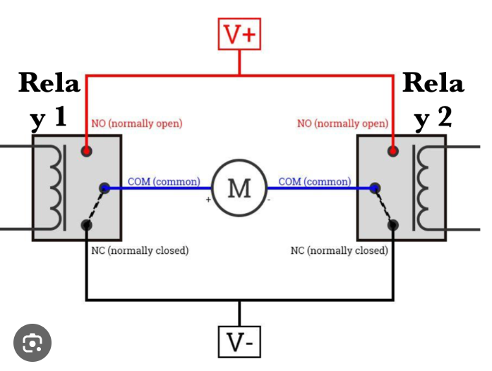
Motor direction control example circuit

The addition of the external buttons


To enable the external controller to activate the motor I tapped in parallel with the buttons so that they would still work if the external buttons were not plugged in.
The drawing below shows how the external buttons were connected in parallel to the existing buttons, I have kept the wire colours as I found them inside the Laser.  The external buttons connector has the pins shorted out so that the internal buttons will also work, if the external buttons are disconnected then they will stop working and a shorting plug would be required.  The interconnecting cable is the one that was provided witht the external stepper controller which I placed inside the laser and was no longer required.


The addition of the height controller

Main components


The last stage of my modification was to add an external controller that could move the Galvo head to a known height that could be entered on my PC.
To achieve this I needed a method of detecting the position of the laser head relative to the base of the laser, after looking into to some laser distance measuring devices that used IR lasers and detectors using TOF (Time Of Flight) measurements to detect range I realised that the accuracy and repeatability for the reasonably priced detectors was not good enough.
I settled on using a Linear scale, a device used on lathes and milling machines to accurately and reliably measure distance for linear movement.
Linear Scale
Linear Scale - sourced from Aliexpress


These devices come in different lengths and I chose 550mm.  The Linear scale is secured to the top and bottom of the Z height tower of the laser using some 3D printed brackets I designed and the moving sled is attached to the Galvo head and moves up and down with the head.  The signals from the linear scale are fed into two interrupt pins of an ATMega328P (as used in the Arduino UNOs) 

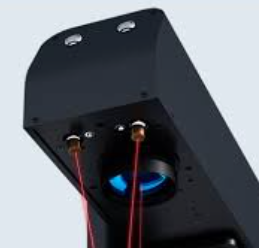
As the Linear scale is a relative measuement method rather than absolute we need a way to define a reference point at a known measurement, to do this I used an inductive sensor that can detect the presence of the metal in the laser head unit and feedback to the controller when the head reaches a known position.
Inductive sensor
Inductive Sensor - Sourced from Amazon

These sensors are also used to stop the motor movement at the extremes of the Z height range.  One thing to note is that these sensors come with a wide voltage supply range but typically start at 6V but I've found that mine work fine at 5V, make sure your choice of sensor does work at 5V.

Component overview

The rendering below shows the position of the components added to the Z height tower (without the tower in the picture)

The controller


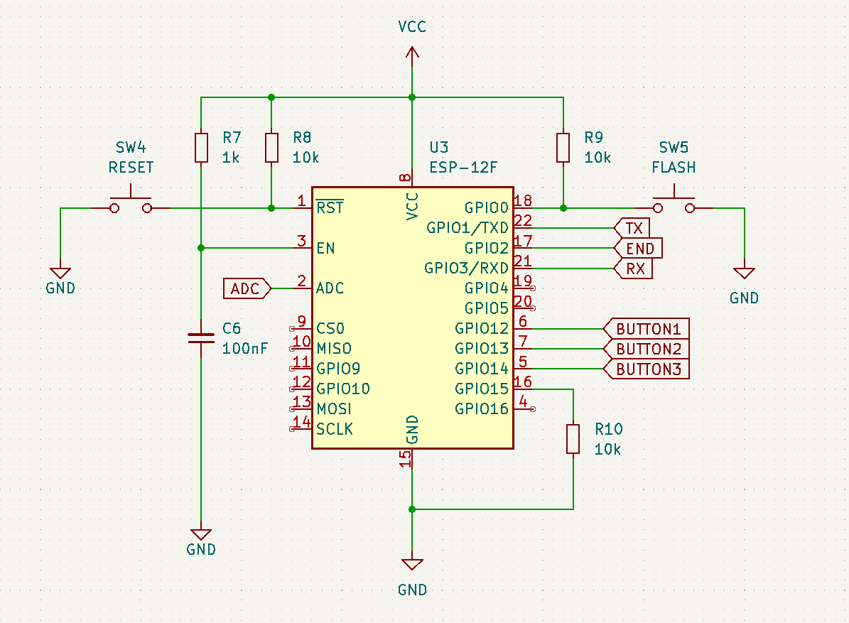
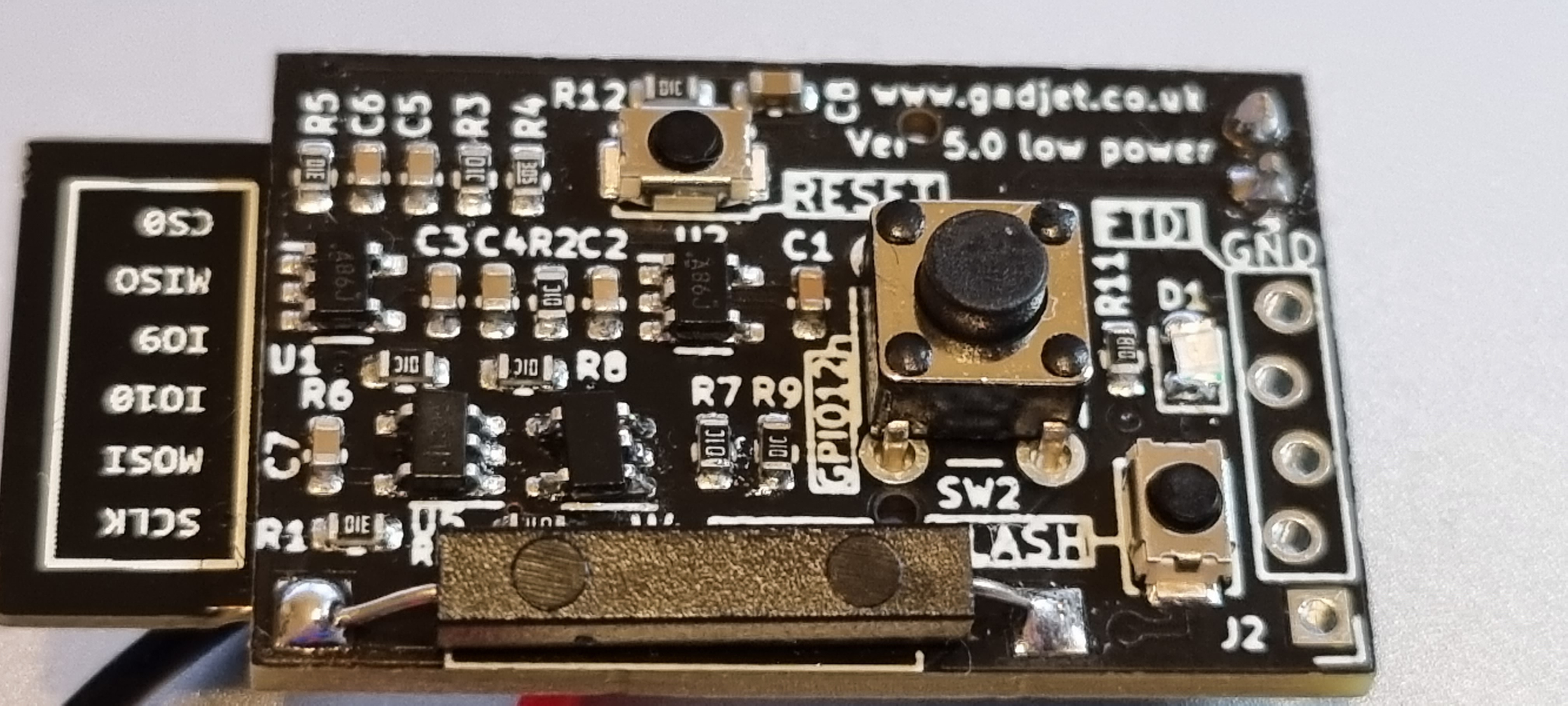
OK so the next thing is to connect all the parts to the controller, the controller is a custom PCB based on an Atmel Mega328p 8 bit processor (Arduino UNO) but you could use an Ardunino UNO, Nano, ESP based processor or any other with suitable IO.
I chose the 328P because it is relatively cheap and available at JLCPCB where I get my PCBs made.
I also included a serial to USB interface so the controller could be connected to a computer and interact with the user via the custom application.
The code I run is, apart from a couple of tweaks, generated by the Google Gemini Canvas AI.


The PCB has the ISP programming connector because the chips have no bootloader code as supplied so this need flashing before you can load a sketch.  There are also connectors for some of the spare GPIOs and the I2C bus so a display could be connected or even a laser distance measuring device if you like but please note that the voltage is 5V and NOT 3.3V.
Although initially the hardware was created with the intention of driving a stepper motor controller I've currently configured the code to drive the DC motor controller in the Laser unit, therefore Down for the motor uses the "DIR" connection and the Up uses the "STEP" connection

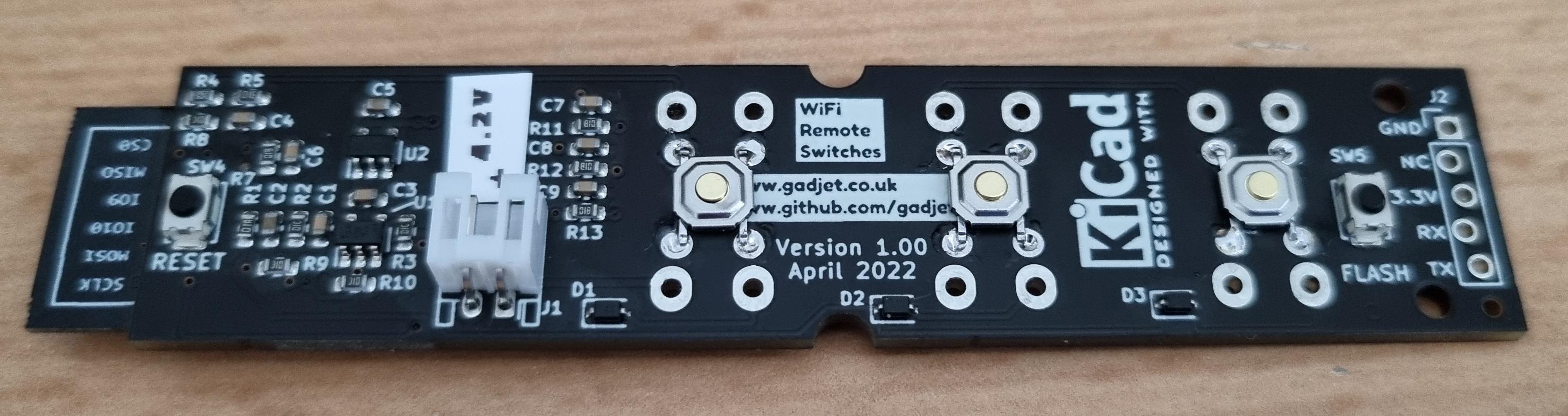
In this second version I added all the screw terminal connections so that each sensor could be connected, you can connect directly to the screw terminals or, like I did, use aircraft type connectors 
  • 2 off 4 pin 12mm connectors for the Limit Switches and the Linear scale
  • 2 off 5 pin 16mm connectors for the external buttons and the motor wires to the laser unit.

PC Software

The PC software is a work in progress and is written in Visual Studio/Visual Basic and connects to the controller via USB allowing 2 way communication, the application displays the mm of movement as the laser head moves up and down and is also used to trigger a fixed distance movement up or down and to calibrate the position of the laser head to a known distance from the base.


The current functions of the PC application: -
  • Display the available comm ports and connect/disconnect
  • Display the position of the laser head in mm
  • Calibrate the distance from the top limit switch to the base
  • Measure the distance from the head to the base and set the height to that value
  • Trigger a fixed distance move in mm from the current position
  • Setup some pre-defined positions on the three configurable buttons
    • Focus position for each lens?
  • Display the text data recieved from the controller in the console window
All the 3D files, Sketch and PC software will be available on my Github within the next couple of weeks.

Please note that this project is a work in progress and may change in functionality as time moves on also I make no guarantees on the functionality and/or safety of this software, use at your own risk.


Wednesday, 9 April 2025

Updates for my Commarker B4 30W fibre Laser

First Mod - move the Stepper controller inside the main unit.

I recently bough a 30W fibre Laser from Commarker and it's great peice of kit for marking and etching metal, something my Creality Diode Laser isn't so good at doing

The fibre laser is a Galvo based laser that uses mirrors to control where the laser lands on the material being etched and is very particular about the focus distance from the lens to the material being etched.

Depending of the lens that is fitted to the Galvo head both the etching area and the focus distance changes, the supplied 110mm x 110mm on my laser has a focus distance of 197mm from the base of the Galvo housing to the top surface of the material being etched, this means that sepending on the thickness of the material the height of the Galvo needs adhusting.

A 500mm ruler is supplied with the laser for you to measure the required distance as well as two focus laser pionters that are angled to meet together when the correct focus distance is acheived.

B4 30W Fibre Laser
   
Focus point lasers

I also bought the add on option of the rotary chuck that links to the laser and allows you to hold a cylindrical object and mark/etch around it, the laser rotates the object whilst etching resulting in allround coverage.

The rotary addon is supplied in two parts, the actual Stepper controlled rotary chuck and the Stepper controller, mounted inside its own aluminiun box. which is connected to the laser main unit with a cable.

So, my first update was to place the stepper controller inside the Laser main unit as the 30W version comes in a tall enclosre and there's loads of room inside to include the stepper controller.

Step1

Remove the Stepper controller from the seperate black box it comes in and make a note of the wire colour connections.

Stepper Controller Wiring


Step2

After removing the galvo assembly and then the Z height tower in a reverse of the assembly process when first put together.

Remove the six hex screws that hold the top on the case and remove the top remembering that the motor for the z height is still attached, place the lid to the side of the box and secure it so it doesn't pull on the wires.

Then de-solder the wires from the 5 pin stepper motor control connector on the back of the laser unit and connected them directly to the Stepper Controller connector.

The Black, Green and Yellow go into one connector and the power wires Blue and Red go into the other two way terminal.

Step3

Remove the 4 way connector from the original stepper controller box and extend the wires so they will reach the other 4 way screw terminal connector on the controller.

Replace the original 5 pin connector with the new 4 pin connector.

DON'T forget to feed the wires through from the rear of the case and add the nut and washer before connecting them to the terminal block.


Step4

Secure the Stepper controller to the base of the main unit with an M4 screw, I used just one at end of the controller nearset the motor controller.

M4 threaded hole to secure the stepper controller

You should now have a single 4 pin connector on the rear of you main laser unit which you connect your rotary chuck to.

While I had the unit apart I also took the opportunity to use the two spare 5 pin connectors to add external access to control the Z height lift motor, details of this mod will be in the next post.


Monday, 23 September 2024

 Time for another post.

A while ago I bought a new Oscilloscope, a RIGOL DHO914, but this scope doesn't have WiFi built in just a LAN connector on thre rear, luckily, as the Scope runs on Android someone has figured out how to get WiFi by using a TP-Link USB WiFi Dongle which, you can plug in the single USB port on the front of the scope.

I found this Youtube video explaining how to enable the WiFi using a plugin TP-link WiFi dongle.

Unfortunately it only has one USB port, you can plug in a WiFi dongle, mouse, keyboard or memory stick but only one at a time.

Now the problem is that I wanted to have the WiFi dongle and a mouse plugged in at the same time so I needed a USB gateway to do this but it's a bit ungainly so I thought I would have a go at making my own USB gateway that fits in with the layout of the scope (I know that they can be bought from Aliexpress for a couple of pounds but where's the fun in that!).  This will allow more than one thing to be  plugged in at the same time.

I found the FE1.1S chip that was a 4 port USB hub controller and JLCPCB had them in stock for $0.55 (£0.41) so I set about designing my own USB HUB.

JLCPCB Part Link

First Attempt


Two port hub

As usual I couldn't wait to get the design done and ordered from JLCPCB  but those eagle eyed amongst you will notice that this device gives me a problem for the DHO914 in that it blocks the Logic Analyser connection port, on the DHO800 series this would be fine as they don't have the Logic Analyser port but for me it will be a problem when I get the Logic Analyser option.

So on to design number 2....

Having proven out that I could make a working USB hub I decided to try and make a design that would better suit the DHO900 Series of scopes, this time I decided on a three port hub with the ports horizontal and below the Logic Analyser port.

Design Render
This design will plug into the single port and still allow the Logic Analyser to plug in although as of today I've not tried it with a Logic Analyser.

The design comprises two PCBs, one for the male USB plug and the other for the three USB sockets, they are connected together using some normal wires (ignore the PCB labels in the render as they are incorrect).  The cover holds the Male USB PCB in place and is screwed from the rear and sides to secure all the parts together.


With the front cover off


All the files including STLs and PCB gerbers etc. are available on Printables.com here.

Saturday, 4 June 2022

Three button WiFi Remote

Using the power control circuit from the Wirelesse door/Window sensor I have designed a simple 3 button WiFi remote with the intention of controlling a couple of WiFi Switches for my TV and a Lamp.

Currently I'm using an aging 433MHz system which is slowly wearing out due to years of usage.

I realise there are many off the shelf solutions out there that I could buy and use but it wouldn't be as much fun as doing it myself although it would probably be alot quicker!

The basic principle of the supply circuit is that the LDO's enable pin is controlled by an OR gate, a positive trigger from one of the three switches fed via a diode, to stop the switch press affecting the other switches, triggers the output of OR gate which in turn enables the LDO and also switches the other OR gate High so the when the original trigger is removed the LDO remeaind enabled.

Power Supply and Triggering

Once the LDO is enabled it powers up the ESP and one of the first things done is for the output controlling the gate to be switched High to keep the gate's output from being switched off, once the code has finished it's job then the output is switched low which causes the OR gate's output to go low and turn off the power to the ESP.


The Buttons

The Buttons are connected individually to the inputs on the ESP and also connected all together via diodes to the Trigger input circuit.


The Schematic shows multiple buttons because I allowed for two types of button to be used, 6mm x 6mm pushbuttons or 12mm x 12mm pushbuttons, you can also use SMD tactile buttons soldered to the footprint of the 6mm buttons.

The ESP

The ESP connections are fairly standard with a Reset button and a Flash button.


Complete Circuit

Here is the overall schematic for the projecy, this one has the additional Pull downs, R15, 15 and 16 that I forgot to add on the first PCB design.

Get the KiCAD files from Github - https://github.com/gadjet/WiFiButtons


PCB

The initial PCB

Get the KiCAD files from Github - https://github.com/gadjet/WiFiButtons


The Mod to add the Pulldown resistors

Unfortunately I forgot to add some pulldown resistors on the original circuit (have been added on the later PCB layout.


The Transmitter Code

The following code sends an ESP-NOW message packet whenever a button is pressed comprising the Device ID, the MAC Address, the button pressed and the battery voltage.  Once the message has been sent the power is turned off by setting GPIO2 LOW.

Get the code from Github - https://github.com/gadjet/WiFiButtons


The Receiver Code

This Code takes the received data from the Transmitter and sends it to the Serial port.

Get the code from Github - https://github.com/gadjet/WiFiButtons

Quiescent Current Profile

The point of the trigger circuit is to reduce the standby current as much as possible so the battery will last as long as possible, this configuration consumes around 1.5uA in standby and an average of 60mA for around 200mS when a button is pressed.


Monday, 28 March 2022

The many versions of the Wireles Door Sensor an Version 5


The Journey so far

I have to admit that it's become a bit of an obsession to try and get this sensor smaller and to use less power at each revision. well I've just finished version 5 which has definitely got the consumption down to a really low level, 3.9uA at its lowest.

Versions 1 to 4 in a row

....... and Version 5
Version 5 assembled PCB


Version 5 has two functions, the normal reed switch trigger so it can be used as a Window/Door sensor and a single button input so it can be used as a Doorbell switch or general WiFi button.

The trigger circuitry combines an edge triggered Monostable circuit from two XOR gates and a single OR gate latch circuit, this latch is triggered either by a pulse from the Monostable or the press of a button which sets the latch.
Once the latch has been set it can then be reset by a LOW signal from the ESP12 when the code has finished running on the ESP12, I used GPIO16 as it is held high during boot.

Schematic

Circuit diagram V5

Using the circuit above the quiescent current of the whole device when there is no magnet next to the reed switch, i.e. door open is 3.90uA and if you were using it as a WiFi connected button then that would be the Quiescent drain, if used as a door/Window sensor then when the magnet is next to the reed switch the quiescent is slightly higher at 5.4uA due to R1 drawing current when the reed switch is closed.

Battery Life

Actual Current consumption

Using a  Nordic Power Profiler Kit II I made some current measurements of the device in the different states: -
Current Consumption Graph


Using an online battery lifetime calculator I found here I calculated these battery times based on a usage of 10 activations per day: -
As you can see the worst consumption will give a battery life of more than 7 years! although this will only be an esitmate and in "real life" I assume there will be other factors that may impact on the battery life but only time will tell but I think you would have a good chance of getting a few years out of a relatively small cell.

The files are available on my Github page


Saturday, 4 December 2021

Door/Window Sensor with an ESP8266

It's been a long time since my last post but I thought I would write up about my latest project - a door/window sensor using an ESP 8266.

I've bought a few door sensors in the past from Tuya and a Hive one (load of rubbish) but I came across a brilliant YouTube video from a gent called MakerMeik who used a logic toggle circuit to wake up the ESP from sleep mode when a reed switch is opened or closed (https://youtu.be/vxbuO1zWo3w).

Using the two XOR logic gates alowed both the door open and door closed to wake up the ESP by toggling the Enable pin whilst also passing the reed switch state to the ESP to publish.

Mike used the ESP to connect to the router via DHCP (or fixed IP) which took a few seconds to establish before then logging onto your MQTT server and publishing the door status.

So I downloaded Kicad and gave it a try, I had tried Kicad a few years ago and was a bit disappointed but the latest version was streets ahead of what I remembered and I soon had a PCB ready to send off for fabrication.

Bare PCB

Populated PCB

The PCBs were delivered and I assembled one which worked as expected (nice surprise) and while I was waiting for the PCBs to arrive back from PCBWay I exported the PCB design as a 3D model (STEP file) which I was able to import into Fusion360 and use as the basis for an enclosure.
Initially my idea was to use an 18650 Lithium cell as I had plenty that I'd reclaimed from old laptop batteries, which still had reasonable capacities, my idea was to use two halves that could be screwed together holding the PCB and battery, this could be screwed to a surface or stuck on with double sided adhesive tape.


The design is quite tall at 33mm but this is OK for my back door which is double glazed and the door is quite deep so the deep back places the reed switch nicely inline with the magnet on the door.
Printed enclosure

Having finished this version of the sensor I've been investigating ways to increase the battery life and reducing the overall size.

I found some smaller batteries that I could use with this design in conjunction with ESP-NOW code that uses alot less transmission time so I designed another rear half that is alot shallower for the new battery.


Smaller rear half for smaller battery

One tip I can give is to buy the plastic encapsulated reed switches instead of the normal glass ones as they are prone to breaking, even though I used surface mount pads to solder the switch rather than having to bend the wires to go through holes.


With my next version I will be trying out the PCB assembly service from JLCPCB so that I can utilise smaller SMD components and not have to solder them together myself!!

Some things I want to improve: -
  • Smaller size
  • Longer battery life and/or smaller battery
  • Add voltage divider to monitor actual battery voltage
  • Have a dual supply solution to use 1.5V AA cell with booster or single 3.6V Lipo cell without booster
  • Learn about ESP-NOW
There are plenty of clever people out there on YouTube with some great ideas around home automation and using the ESP8266 and ESP32 so time to watch some videos.

Gerbers, STL files etc. available from here https://1drv.ms/u/s!AkqVSEM4Y7kDhuZ0Lg1CdJrBs745Ug?e=ACkTkJ

The code for the device is available from MakerMeik's GIThub page, watch his video.

Version 2 coming soon .......


Sunday, 14 May 2017

Hot water control using a Raspberry Pi Zero W


Following on from the first blog about the hot water heating control here's what I put together for the mounting.
Whilst looking for a suitable enclosure I came across an surface mount electrical socket back-box and I got to thinking "how can I mount the RPi W and relay in this?" so after some head scratching I thought about 3D printing some carriers to go inside the back-box.
The picture above shows two carriers printed to support the RPi and the relay board.

Then I made the required entry holes in the back-box for the power cable (USB), the mains switching cable for the relay and the temperature sensor cable.

This contraption has been sitting on my desk for a few weeks running quite happily and I've been checking the event log to make sure it's been switching on and off when it should.

Next to interface it to the existing wiring.

Updates for my Commarker B4 30W fibre Laser

 Second Mod - Add external buttons and an automated height controller ******* PLEASE NOTE ********* I did this with my B4 30W laser unit, I ...

Popular Posts