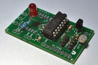
I've now gone into the symbol for the RF12B and added a couple of mm to the package outline and improved the PCB layout by rotating R3 90 degrees to clear the RF12B PCB. Ready for the next batch, if I ever need any more!
I programmed a blink sketch into an '84 and plugged into a PCB, added an LED between PB0 and
Next job is to add the RF12B and start to read temperatures from the DS18B20(s) and get them transmitting.
I've also ordered some 2xAAA battery holders with switches from ebay so I can easily power the boards.
If all goes well I will even have a go at logging data to an SD card, another ebay purchase.


No comments:
Post a Comment