Using the power control circuit from the Wirelesse door/Window sensor I have designed a simple 3 button WiFi remote with the intention of controlling a couple of WiFi Switches for my TV and a Lamp.
Currently I'm using an aging 433MHz system which is slowly wearing out due to years of usage.
I realise there are many off the shelf solutions out there that I could buy and use but it wouldn't be as much fun as doing it myself although it would probably be alot quicker!
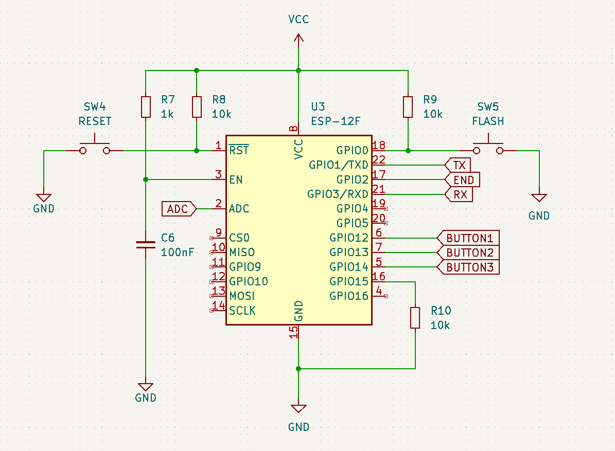
The basic principle of the supply circuit is that the LDO's enable pin is controlled by an OR gate, a positive trigger from one of the three switches fed via a diode, to stop the switch press affecting the other switches, triggers the output of OR gate which in turn enables the LDO and also switches the other OR gate High so the when the original trigger is removed the LDO remeaind enabled.
Power Supply and Triggering
Once the LDO is enabled it powers up the ESP and one of the first things done is for the output controlling the gate to be switched High to keep the gate's output from being switched off, once the code has finished it's job then the output is switched low which causes the OR gate's output to go low and turn off the power to the ESP.

The Buttons
The Buttons are connected individually to the inputs on the ESP and also connected all together via diodes to the Trigger input circuit.

The Schematic shows multiple buttons because I allowed for two types of button to be used, 6mm x 6mm pushbuttons or 12mm x 12mm pushbuttons, you can also use SMD tactile buttons soldered to the footprint of the 6mm buttons.
The ESP
The ESP connections are fairly standard with a Reset button and a Flash button.
Complete Circuit

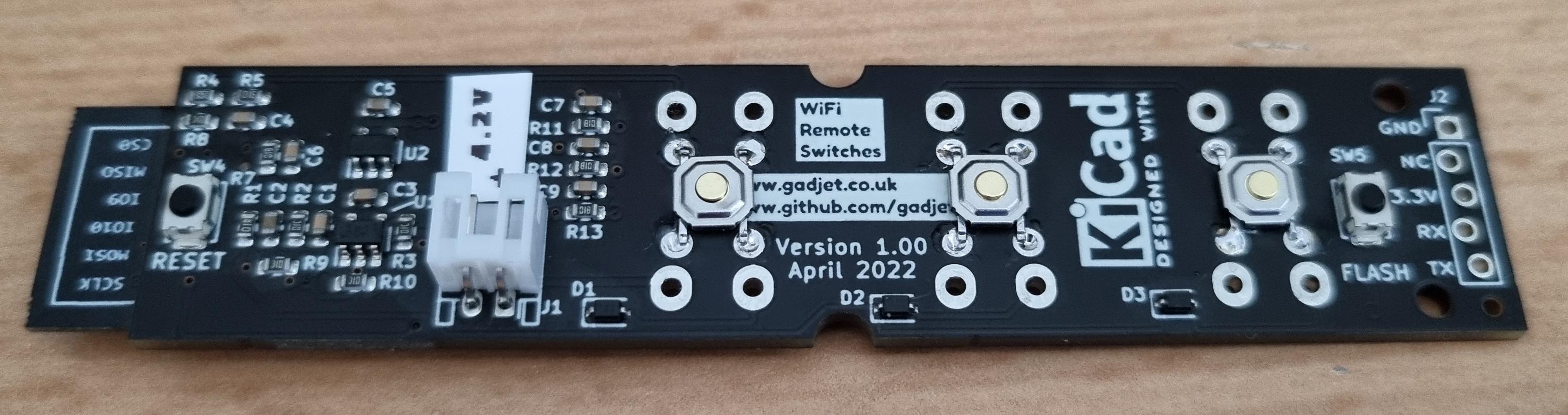
PCB
The initial PCB
Get the KiCAD files from Github - https://github.com/gadjet/WiFiButtons


The Mod to add the Pulldown resistors

The Transmitter Code
The following code sends an ESP-NOW message packet whenever a button is pressed comprising the Device ID, the MAC Address, the button pressed and the battery voltage. Once the message has been sent the power is turned off by setting GPIO2 LOW.
The Receiver Code
This Code takes the received data from the Transmitter and sends it to the Serial port.
Quiescent Current Profile


4 comments:
Nice work!
Which function has the extra circuits (cap and resistor) parallel to the buttons? Debounching?
Thanks.
Yes the resistor/Capacitors are debounce.
Hello,
I'm Wendy from the marketing team of PCBWay, a global electronics manufacturing services company. You can learn more about our process capabilities by following this link: https://www.pcbway.com/capabilities.html.
It is a pleasure to visit your website and find its content very relevant to our profession. We wonder if there is an opportunity here to work with you, and PCBWay would like to sponsor your next electronics project, would you be interested in this?
We look forward to your reply.
Hi Wendy,
Yes I would be interested, how would it work?
Phil
Post a Comment