Tuesday, 24 July 2012

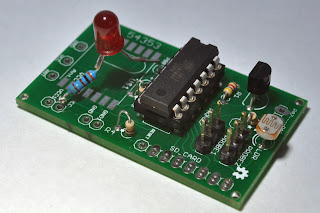
ATtiny board blinking

Well I got around to adding some components to the PCB, and found a couple more "improvemments" that can be made.  They're mainly around the package size of the RF12B transceiver, even though it was pointed out in other blogs I fell into the same trap, I moved the battery connections down a bit to clear the RF12B but forgot about the top so that the lower leg of R3 has a hard clash with the top of the RF12B PCB.

I've now gone into the symbol for the RF12B and added a couple of mm to the package outline and improved the PCB layout by rotating R3 90 degrees to clear the RF12B PCB. Ready for the next batch, if I ever need any more!

I programmed a blink sketch into an '84 and plugged into a PCB, added an LED between PB0 and VCC GND and it actually worked.

Next job is to add the RF12B and start to read temperatures from the DS18B20(s) and get them transmitting.

I've also ordered some 2xAAA battery holders with switches from ebay so I can easily power the boards.

If all goes well I will even have a go at logging data to an SD card, another ebay purchase.
Thursday, 19 July 2012

Multi purpose ATtiny84 PCB

Thanks to stumbling across a couple of ATtiny84 blogs here nathan.chantrell.net and here http://harizanov.com  I was inspired to create my own PCBs for an ATtiny84 chip.

The biggest inspiration was the link to an extremely cheap site for the production of PCBs, in fact 10 off 5cm x 5cm only cost $13 inc. postage.  Ten PCBs for a tenner, Fantastic. Link

I used the Eagle files from Nathans site and modified them to suit my requirements by adding the connections for an SD card, a CR2032 battery holder, 2 extra DS18B20 probes and an LDR, both the DS1820s and LDR have switched power supply using an output pin. (idea from Martin's corner of the web)

The finished PCBs arrived today and they look pretty good.

I'll build one up later next week and get programming.

My next PCB is an add on board for my USBtiny ISP programmer so I can program a 328P, ATtiny84 or ATtiny85.

If anyone wants the eagle files for the PCB below then just let me know in the comments.

Schematic

PCB

OOPS! noticed that the labels for the VCC, VCC1 and GND, GND1 are swapped over, the top pair are actually VCC and the lower pair are actually Grounds

3D rendering in Google Sketch up

Actual finished PCBs

Here is a link to the files.

Tuesday, 3 July 2012

Updated Set time on the DS1307 and the Arduino

Some time ago I posted a Windows application to run on the PC which would integrate with a sketch on the Arduino platform to set the time on a DS1307 RTC chip. here

Well I started to play with the RTC again today and I made some changes to the application and noticed there was an update to the sketch found here. The Site seems to be down so here's another link to the file DS1307 Sketch.

I've added buttons to read the time/date out and clear/dump the memory to the text box, now it even saves the com port and baudrate settings for the next time you open it up.


Feel free to try it out and let me know if it doesn't work etc. and I'll do my best to fix it.

The software can be downloaded here.

 Time for another post. A while ago I bought a new Oscilloscope, a RIGOL DHO914, but this scope doesn't have WiFi built in just a LAN co...

Popular Posts